To create an Arduino Timer Interrupt, we need to decide two things,
- the time between Interrupts (or its frequency)
- the Timer we want to use.
In the Video-Intro for RTM_TimerCalc, I chose 1000 milliseconds (which is 1 Second) and selected Timer-1. After that, I generated sketch code and uploaded it to a Mega 2560.
Since you may be using a Nano or Uno instead, remember those MCU cards can only use Timer1 and Timer2 -- while the 2560 has 5 Timers available.
Arduino Timer Interrupt with a 16-Bit Timer
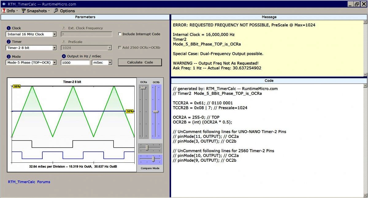
For long Interval Interrupts like 1 Second, we want to use a 16 bit Timer. It can count to 65,535 where an 8 bit can only count to 255. That's a huge difference in Timing range. If you ask RTM_TimerCalc to give a 1-Second Interrupt using Timer-2, it will warn you the best you can hope for is roughly 32 milliseconds! That's way shorter than 1000 milliseconds. Here's an image of that calculation (click to enlarge).
As shown in the message window, there is no way an 8-bit Timer can deliver on 1000 milliseconds (at this clock frequency). But if we are looking for a shorter time (say 1, 2 4 or 8 milliseconds), then an 8-bit counter would work fine.
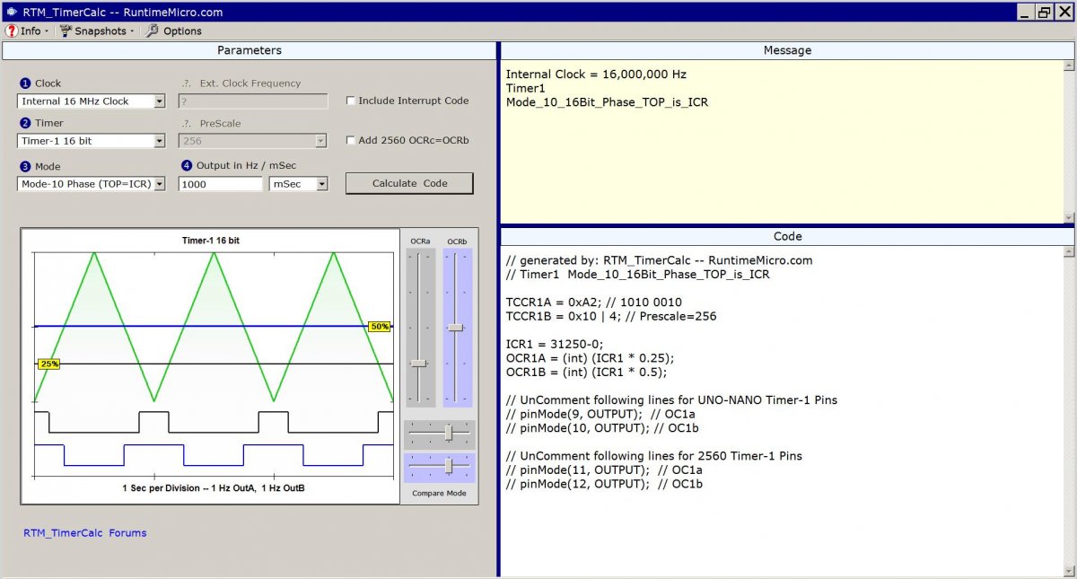
So that leaves us using a 16-bit counter like Timer-1 (found across all three MCU boards). When we ask for a 1000 millisecond Interrupt, it works just fine. See the next image.
Image Path: /sites/default/files/Forum%20Images/SemiCorrectSetup.jpg
Alt Text: Image shows Timer-1 Interval Interrupt setup but with extra code.
Output Waveforms not Needed
So, lets take this a step further. The above images show code that includes waveform outputs. But we don't need waveforms for an Interval Interrupt. Worse still, I didn't check the "Include Interrupt" checkbox so the Timer interrupt code wasn't generated.
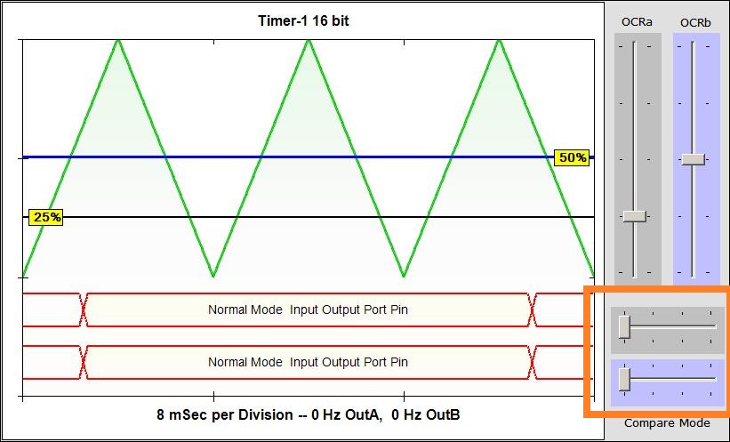
To fix these issues, I'll set the Output Compare Mode sliders to full left. That turns off the waveforms. Next Image shows what it looks like.
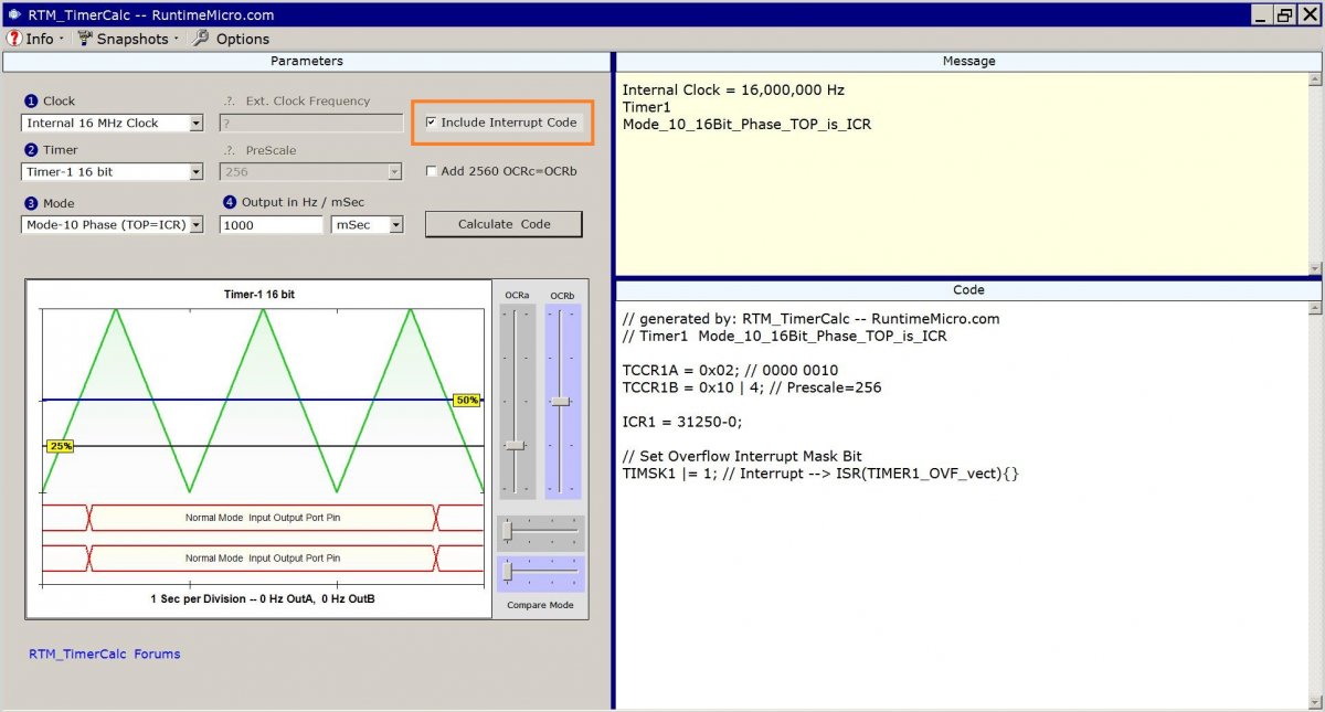
And I'll check the box for Including Interrupts and then re-calculate the code. See next Image...
As you can see, we have a lot less code generated. And we have no warnings in the Message Window. So, that should mean we're good to go.
Now we copy generated code from the Code Window and paste it into our IDE. We also need to have in mind some way to use our Interrupt. For this example, I just made the LED at Pin-13 flash on and off. Here's the resulting source code for this example (fleshed out and tested).
int volatile SecondsVar;

ISR(TIMER1_OVF_vect)
{
SecondsVar++;  // <<--- Interrupt variable gets incremented
}

void setup()
{
//-------------------------------------------------------
// RTM_TimerCalc 1.40,  RuntimeMicro.com
// Timer-1 16-bit, Mode-10 Phase, Top=ICR
// 1,000 mSec Interval, Clock is 16 MHz

TCCR1B = 0x10; // 0001 0000, Disable Timer
TCCR1A = 0x02; // 0000 0010

ICR1 = 31250-0;
TCNT1=0x0;

// Set Overflow Interrupt Mask Bit
TIMSK1 |= 1; // ISR Prototype --> ISR(TIMER1_OVF_vect){}

TCCR1B |= 4; // Prescale=256, Enable Timer
//-------------------------------------------------------

pinMode(13, OUTPUT); // LED pin set for Output
}

void loop()
{
digitalWrite(13, SecondsVar & 1); // LSB of SecondsVar drives LED ON and OFF
}|
The above code shows how you can quickly create an Arduino Timer Interrupt. What I did (in loop) was logically AND the Least-Significant-Bit (LSB) of the SecondsVar variable with a value of 1. Whenever the variable has its LSB holding a value of 1, the digitalWrite command sets the port-pin output to illuminate the LED. When the value is Zero, we are writing a value of Zero to extinguish the LED. The result shows that the hardware of Timer1 is under -your- control. RTM_TimerCalc lets you decide the Timer, the Interval and whether the port-pin connects to the Timer or is under sketch control.
Have fun creating Arduino Interrupts,
Lee
