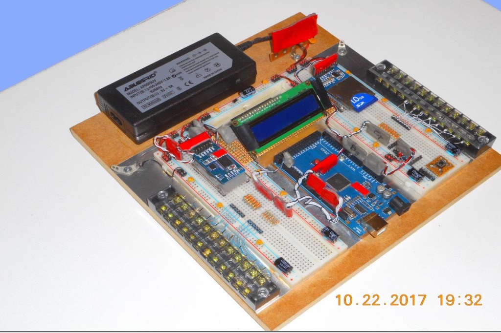
Shown above is a Permanent Solderless Breadboard project. It has external connections for Digital and Analog signals. Plug-in Carriers support modules for LCD, Clock-Calendar and Secure-Disk. Though 99% free of soldered wires, this 10-by-10 inch build will operate for many years. Yet, its fairly easy to take apart and re-assemble should repairs or changes be needed.
Permanent Solderless Breadboard?
Wordweb defines 'permanent' as; "Continuing or enduring without marked change in status or condition or place...". And that essentially describes results obtained with this construction technique.
The Permanent Solderless method combines Breadboards, thru-hole Headers and Wire-Wrap to make resilient electronic projects. Because flimsy jumper-wires are eliminated, circuits are more tolerant of impact and vibration. And that translates into long lasting builds with decent reliability.
Are Thru-Hole Headers Suitable for Wire Wrap?
Yes! Thru-hole Headers have tenth-center spacing and square .025 inch posts. They can be inserted (with care) into AWG #21-22 compliant Breadboards. And since Headers come in break-away form, we can snap off sections from 2-to-40 pins at a time.
Which Headers When?
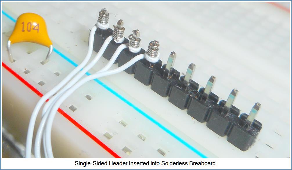
I rely on Double-sided and Single-sided male Headers (shown next).
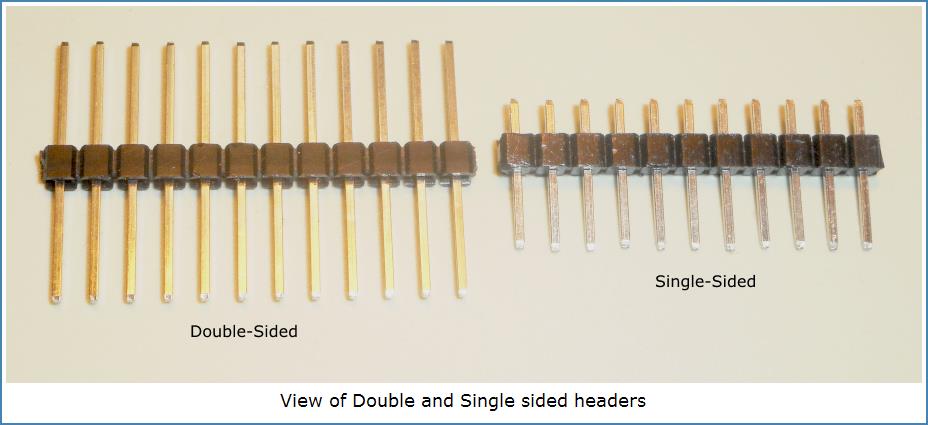
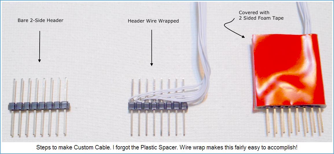
Double-sided Headers are best for making plug-in Custom Cables. Cables are crucial for interconnecting MCU headers, Module headers and Breadboards. Using techniques outlined here, you'll find making Cables is fairly easy once you learn wire-wrap.
Single-sided Headers are useful for making fixed point-to-point connections where wire-ends never move. More on all this follows next.
Permanent Solderless Breadboard Techniques
The following paragraphs outline durable methods you can apply to your Hobby Micro Projects.
Point to Point Wiring
We don't want jumper-wires! They're bulky, unreliable and hard to redress for neat appearance. Instead, we'll wire wrap to Single-side Headers placed where a jumper-wire would be used.
The guideline for choosing point-to-point wiring is: both ends of the wrapped wire must connect to a non-moving posts. But if either wired post needs to move (or disconnect), then we must use Custom Cable plugs for both wire-ends.
MCU to Outside World
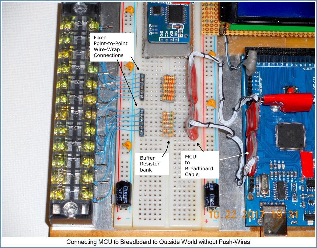
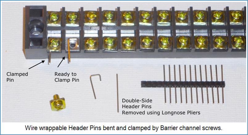
Some Projects may need to run MCU lines off platform. We can accomplish this starting with a Cable for MCU-to-Breadboard. Then a set of buffer resistors is placed where the cable plugs into the Breadboard. The other side of the resistors meet up with an inserted Single side Header. The Header posts are wire-wrapped to Barrier clamped posts. (next image)
Custom Cables
Cables are important! They make connecting MCU, Breadboards and Modules a straight-forward task. They help you disconnect and replace circuitry in a modular fashion. Making them yourself saves time and money! Detailed instructions for Custom Cables using Permanent Solderless Tactics.
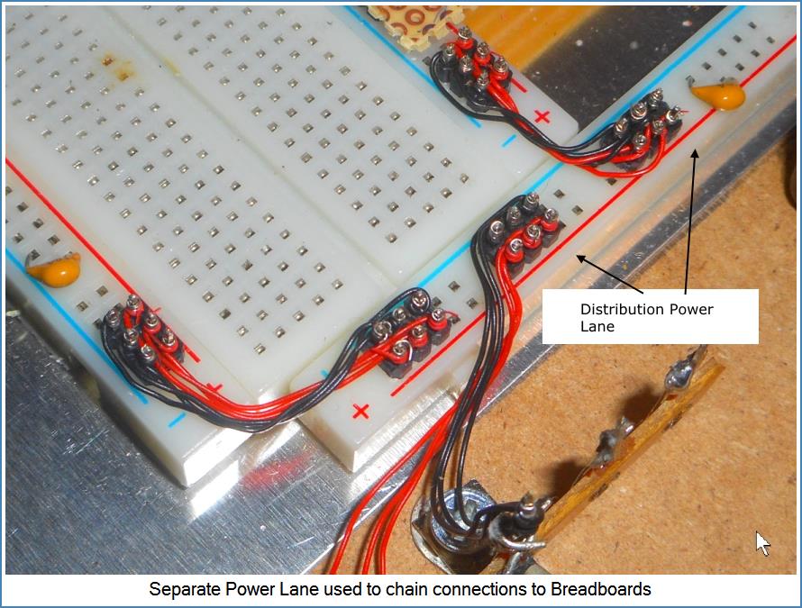
Power Lane Wiring
Solderless Power Lanes can be chained together using parallel #30 wires. Each wire handles approx. 100 mA of current. I recommend using 2-row Single-sided Headers for this task. I allow 3 connections for power and 3 connections for ground. This seems to work well and uses little space. Voltage drop is negligible.
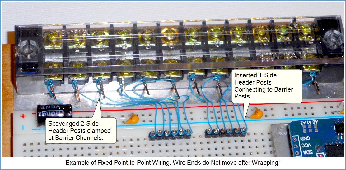
Wire-Wrapping to Barrier Strips
Double-sided Header pins, clamped to Barrier channels provide the ability to wire-wrap connections. The scavenged Header pins are bent into a -J- shape for clamping. Now your internal wiring has a rugged way to reach the outside world See next image.
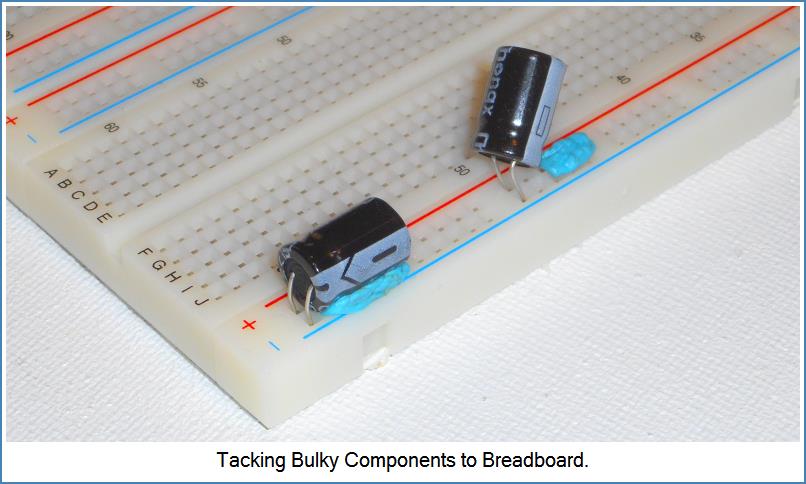
Floppy Discrete Components
Solderless projects often use bulky thru-hole components like electrolytic capacitors. The electrical connection works but component mounting is flimsy. We solve this by tacking components to breadboard plastic using modern adhesives such as, Fun-Tak or 2-side Sticky tape. In cases where this doesn't work, a component Carrier solution is a good option.
Component Lead Diameter
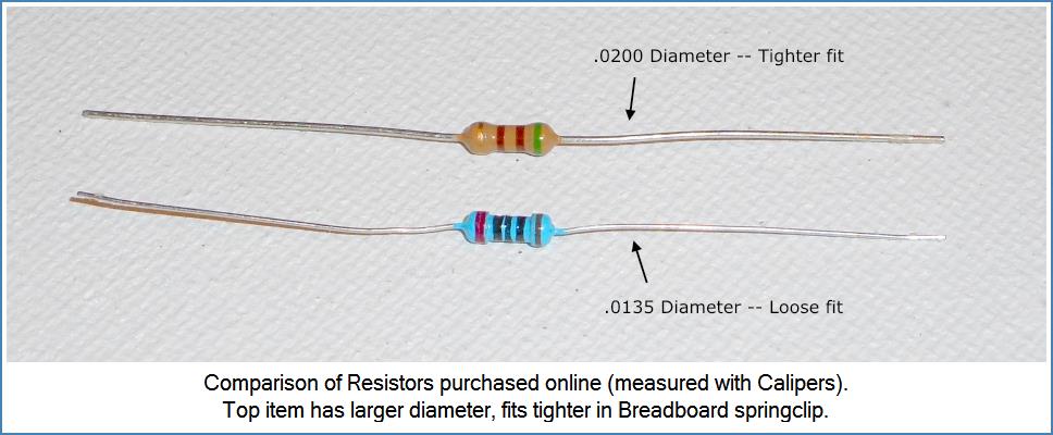
Some resistors use diameters so small they can exhibit intermittent operation in marginal Breadboards. In one of my builds, I used a not-so-great Breadboard. When turned upside down, resistors of .0135 lead-diameter fell out!. The solution was to use components whose lead diameters result in solid Breadboard spring-clip tension. The next Image illustrates...
Plug-in Carriers for Built Modules
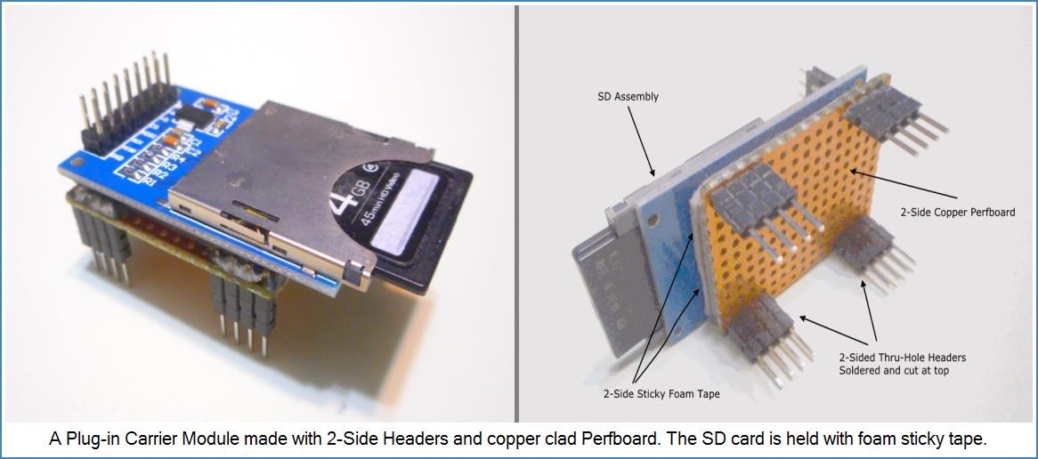
There are tons of already built low-cost Module circuits available for Hobby builders. Modules can boost Project functionality. A problem though is how to mount them? One answer is place them on Carriers.
Custom plug-in Carriers are easy to make by combining thru-hole Headers with copper clad perfboard. A bit of soldering and pin cutting quickly creates a reusable plug-in platform. You control clearance between Carrier and Breadboard using scavenged plastic spacers from extra Header sections.
I apply several layers of foam sticky tape to attach Module circuit boards to Carrier platforms. Then a Custom Cable connects it to MCU or Breadboard. Carriers are rugged -- yet easy to reposition (or remove) should the need arise.
Handling Bus Signals
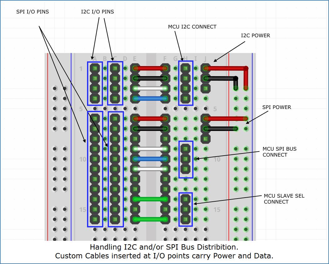
Connecting circuit areas with Bus Signals such as SPI and I2C can be tricky. Breadboard areas can distribute these Signals to Custom Cables. The following text describes a way to provide 2 Cable (sockets) each for SPI and I2C. Rectangular borders shown in the image indicate Custom male Cables plugged into the Breadboard.
Cables from MCU bring in I2C, SPI and slave-select lines (right side of image).
Added Power connections from power-lane become part of hookup (right side as well).
Bus I/O and Power connections bridge to left side using fixed point Header connections (center of image).
Cables can connect 2 (SPI plus Power) and 2 (I2C plus Power) at left.
Please note: The SPI Bus may need to run at reduced speed if distributed via Breadboard. For high speed SPI, you may need a pure-wire-wrap or Strip-board circuit mounted on a module carrier.
Please note: The SPI Bus may need to run at reduced speed if distributed via Breadboard. For high speed SPI, you may need a pure-wire-wrap or Strip-board circuit mounted on a module carrier.
Permanent Solderless Summary
- Breadboard based Projects can be rugged and durable using wire-wrapped Headers to replace jumper-wires!
- Custom Cables account for removable wiring between MCU, Modules and Breadboard.
- Bulky components are securely attached using removable adhesives (or placing on a Carrier).
- Plug-in Carriers hold built Modules for easy placement or removal.
- You're not stuck in a soldered situation. Changes are easier to accomplish -- even years later.
- You avoid the time and cost of rebuilding in Stripboard or Printed circuit form.
- Its not expensive to get started.
PLAY IT SAFE!
- Please Use Caution when inserting headers into Solderless Breadboards. Combined resistance of multiple pins may require using considerable force. Use care and protect your hands!
- Please Don't leave Header pins or stripped insulation lying around as Toddlers may try to swallow them (choke hazard)!
- Please Don't leave Breadboards with Inserted pins in areas where a body part may get punctured!
