
Here's an Uno Phase Shift PWM (PSPWM) project with surprising features;
- Uses Timer1 only
- Selectable 2, 3, 4, 5, or 6 channel output
- Selectable 50, 60, 300, 400, 500, 600 Hz channel rate.
- Forward-Reverse sequence,
The project employs Hardware-Assisted-Code to generate a variety of Phase Shift PWM outputs. But there's a catch -- output duty cycle is limited to pulse widths with no overlap. Duty is also limited to around 1-2% as a minimum. Plus other Interrupts (like Timer0) can cause pulse width variations.
You may find these limitations unacceptable. But if you're curious, read on for details, code, schematic and images
Phase Shift PWM from Hardware Assisted Code
Uno's Timer1 waveform generator outputs stable PWM signals. We can use its COMPa pulse-edge interrupts to make duplicate PWM pulses. The duplicates are slightly delayed but easy to output to Port-D via a selector-byte write. (see next diagram)

The selector-byte has a single HIGH bit sequentially shifted by COMPa's ISR. When the byte gets written to Port-D, only one pin goes HIGH. A subsequent (falling edge) COMPa interrupt writes Port-D pins LOW. Repeated shifts-and-writes create software-realized Phase Shift PWM.
Abilities and Limitations
Because ISR code controls pulse generation, we gain some interesting abilities;
- PSPWM Output across 2, 3, 4, 5, or 6 channels.
- Automatic phase-angle determination for channel choices; 2=180, 3=120, 4=90, 5=72 and 6=60 degrees.
- Forward or reverse sequence direction
- Selectable channel frequencies at or below 600 Hz.
However, remember the catch! As you add channels, you reduce duty-cycle range. One way to calculate your duty-cycle maximum is:
DutyMax = ((99% / NumChannels) - Small_Delta).
The resulting pulse width approaches (but can never reach) a condition of channel-to-channel overlap. This limitation doesn't exist using multiple-Timer Phase Shift PWM. But with a single Timer, we sacrifice duty range. In some situations, this may be acceptable.
Another limitation is Interrupts other than COMPa (like those from Timer0) may interfere with software timing causing seemingly random pulse variations. Clearing Timer0's Interrupt Mask helps -- but forfeits many Arduino facilities like Delay(). This means you must be super-careful with Interrupts while this sketch is running.
Phase Shift PWM Performance
I wanted stable PWM waveforms with no drop-outs or pulse-width anomalies. By staying away from duty-cycle extremes (1-to-3% margins), output remained fairly stable. If you could reach Timer1's true Min-Max duty, there's not enough CPU time to handle housekeeping -- COMPa interrupts get too close together.
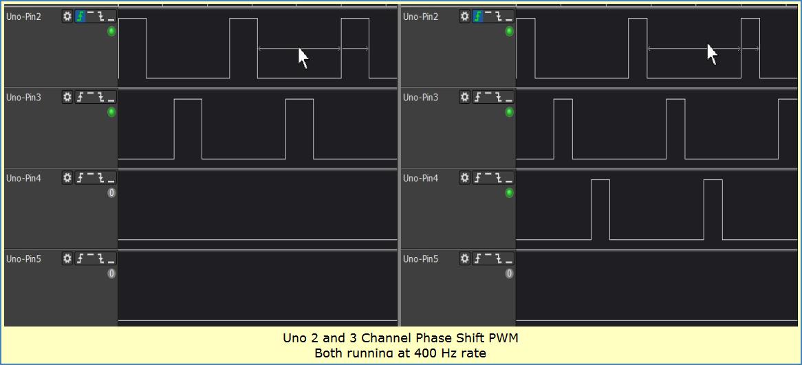
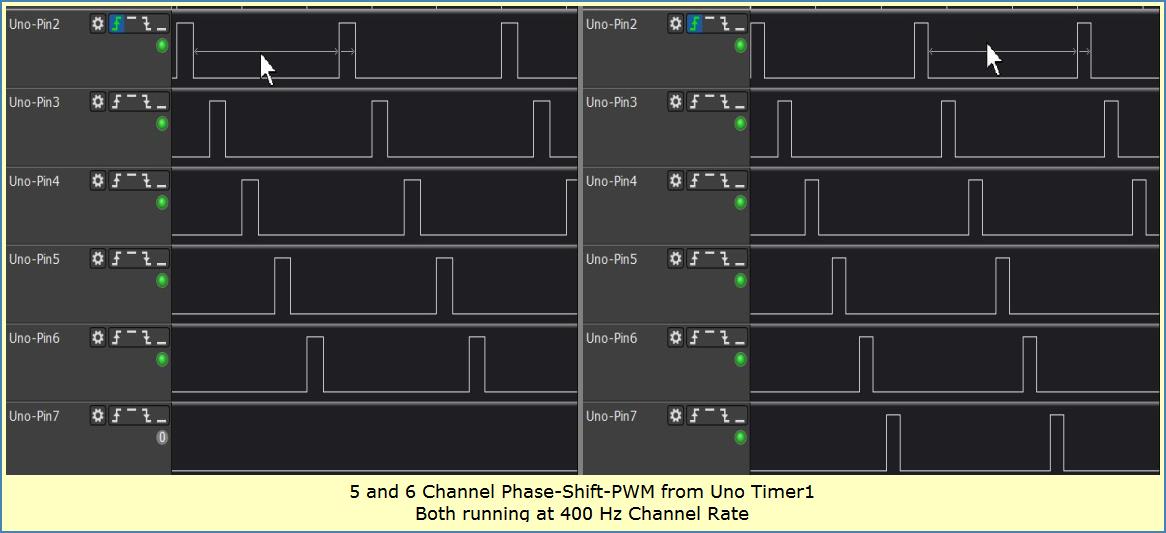
Here's some logic Analyzer snapshots showing what an Uno can do running this sketch. Note the pin number designations. Imagine what an MCU running high clock-speed could do!
Channels and Direction

Startup and Pulse Cloning

Uno Phase Shift PWM Build
I rewired a previous project (using Permanent Solderless wire-wrap) to realize the build. The Uno handles all PSPWM tasks. We just add a few wires to break out signals.
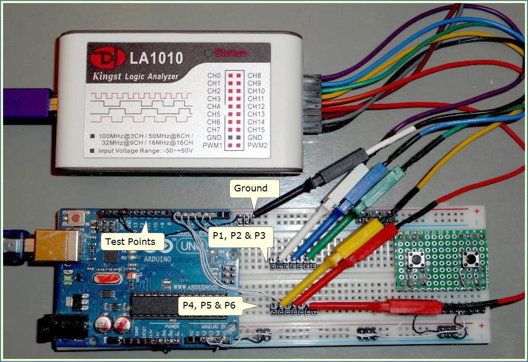
Included were several Test-Point signals;
- Timer OC1a PWM output. Handy to analyze pulse aberration comparing Hard-Pulses with Soft-Pulses.
- Overflow interrupts from Timer-1 to spot pulse centers. Great to demo pulse-width changes staying center-symmetric.
- A marker pulse from setup() to capture start-up behavior.
Uno Phase Shift PWM Code
Combine the following sketch with the wiring diagram shown below to duplicate these results. You must un-comment a single #define for selected Frequency and another single #define for selected Channel-Count. Then compile and upload.
The sketch multiplies channel count and channel frequency to derive Timer1's cycle-frequency. A look-up operation sets variables for Pulse generation in a given direction and phase-frequency. The number of channels determines sequence phase-angle.
The sketch fires a setup marker-pulse to capture start-up behavior. It also enables an overflow interrupt to provide pulse center-markers. Neither of these markers is needed for general operation and can be disabled.
In loop(), the push-buttons modify a variable that gets passed in the main ISR. Passing duty-changes in the ISR keeps Pulse generation stable and predictable while push-buttons are active.
Arduino loop() is doing nothing beyond push-button sensing and duty-cycle adjust. You can add code to do whatever else you want. Just remember, the Timer COMPa interrupt must not be messed up by other Interrupt ISR's hogging time! Be sure you keep all other Interrupts (super short). Timer0 Interrupts are running fine in the background AFAICT. But you could mask out Timer0 Interrupts if you feel they cause instability to PWM generation.
// Uno Phase Shift PWM, Hardware Assisted Code (HAC)
// Single 16-bit Timer
// Selectable 2-thru-6 Channels
// 50, 60, 300, 400, 500, 600 Hz Freq
// Timer parameters calculated by RTM_TimerCalc V1.4
// Choose PHASE-CYCLE FREQUENCY
//------------------------------------------
// unsigned int CHANNEL_FREQ_HZ = 50; // 20 mSec
// unsigned int CHANNEL_FREQ_HZ = 60; // 16.6 mSec
// unsigned int CHANNEL_FREQ_HZ = 300; // 3.3 mSec
unsigned int CHANNEL_FREQ_HZ = 400; // 2.5 mSec
// unsigned int CHANNEL_FREQ_HZ = 500; // 2.0 mSec
// unsigned int CHANNEL_FREQ_HZ = 600; // 1.7 mSec
// Choose NUMBER-PWM-CHANNELS
//---------------------------------------------------
// unsigned int NUM_PWM_CHANNELS = 2; // 180 degree, max duty < 50%
// unsigned int NUM_PWM_CHANNELS = 3; // 120 degree, max duty < 33%
unsigned int NUM_PWM_CHANNELS = 4; // 90 degree, max duty < 25%
// unsigned int NUM_PWM_CHANNELS = 5; // 72 degree, max duty < 20%
// unsigned int NUM_PWM_CHANNELS = 6; // 60 degree, max duty < 16%
// Choose SHIFT DIRECTION
//-------------------------
#define SHIFT_DIRECTION_FWRD 1 // forward dir, pulses begin at pin-2
#define SHIFT_DIRECTION_REVS 2 // reverse dir, pulses end at pin-2
unsigned int SHIFT_DIRECTION = SHIFT_DIRECTION_FWRD; // <<***********
// Declare Other Variables
//---------------------------------------------------
volatile unsigned long TimeClock; // incremented by Pulse ISR
unsigned long TimeCount; // number ticks of Time to pass 20 mSec
//---------------------------------------------------
unsigned int btn_DutyIncrease_Pin = A3; // Using ADC pins for push-buttons
unsigned int btn_DutyDecrease_Pin = A5;
unsigned int Duty_Limit_LOW; // LIMITs for adjustable duty range
unsigned int Duty_Limit_HIGH;
unsigned int DUTY_CHG_RATE; // Rate of Duty Change using push-buttons
unsigned int N_Divide;
unsigned int PreScale;
unsigned int TIMER_CYCLE_FREQ_HZ;
float Upper_Limit_Duty;
// Declare ISR Variables
//----------------------------------------------------
volatile byte SHIFT_OVF; // forward dir preset -- chan-count dependent
volatile byte REV_PRESET; // reverse dir preset -- chan-count dependent
volatile byte Selector_Byte; // byte to output pulses to Port-D
volatile unsigned int OCR_Result; // duty-cycle calculation and storage
void SetTimerControlParams(unsigned int TimerCycleFrequency)
{//=========================================================
// N_Divide, PreScale values calculated by RTM_TimerCalc v1.4
switch(TIMER_CYCLE_FREQ_HZ)
{
case 100: N_Divide=10000; PreScale = 2; Upper_Limit_Duty = 0.99; TimeCount =2; break;
case 120: N_Divide=8333; PreScale = 2; Upper_Limit_Duty = 0.99; TimeCount =2; break;
case 140: N_Divide=57143; PreScale = 1; Upper_Limit_Duty = 0.99; TimeCount =3; break;
case 150: N_Divide=53333; PreScale = 1; Upper_Limit_Duty = 0.99; TimeCount =3; break;
case 160: N_Divide=50000; PreScale = 1; Upper_Limit_Duty = 0.99; TimeCount =3; break;
case 180: N_Divide=44444; PreScale = 1; Upper_Limit_Duty = 0.99; TimeCount =4; break;
case 200: N_Divide=40000; PreScale = 1; Upper_Limit_Duty = 0.99; TimeCount =4; break;
case 240: N_Divide=33333; PreScale = 1; Upper_Limit_Duty = 0.99; TimeCount =5; break;
case 250: N_Divide=32000; PreScale = 1; Upper_Limit_Duty = 0.99; TimeCount =5; break;
case 300: N_Divide=26667; PreScale = 1; Upper_Limit_Duty = 0.99; TimeCount =6; break;
case 360: N_Divide=22222; PreScale = 1; Upper_Limit_Duty = 0.99; TimeCount =7; break;
case 600: N_Divide=13333; PreScale = 1; Upper_Limit_Duty = 0.98; TimeCount =12; break;
case 800: N_Divide=10000; PreScale = 1; Upper_Limit_Duty = 0.98; TimeCount =16; break;
case 900: N_Divide=8889; PreScale = 1; Upper_Limit_Duty = 0.98; TimeCount =18; break;
case 1000: N_Divide=8000; PreScale = 1; Upper_Limit_Duty = 0.98; TimeCount =20; break;
case 1200: N_Divide=6667; PreScale = 1; Upper_Limit_Duty = 0.97; TimeCount =24; break;
case 1500: N_Divide=5333; PreScale = 1; Upper_Limit_Duty = 0.97; TimeCount =30; break;
case 1600: N_Divide=5000; PreScale = 1; Upper_Limit_Duty = 0.96; TimeCount =32; break;
case 1800: N_Divide=4444; PreScale = 1; Upper_Limit_Duty = 0.96; TimeCount =36; break;
case 2000: N_Divide=4000; PreScale = 1; Upper_Limit_Duty = 0.96; TimeCount =40; break;
case 2400: N_Divide=3333; PreScale = 1; Upper_Limit_Duty = 0.96; TimeCount =47; break;
case 2500: N_Divide=3200; PreScale = 1; Upper_Limit_Duty = 0.96; TimeCount =50; break;
case 3000: N_Divide=2667; PreScale = 1; Upper_Limit_Duty = 0.96; TimeCount =61; break;
case 3600: N_Divide=2222; PreScale = 1; Upper_Limit_Duty = 0.96; TimeCount =71; break;
}
}//--end SetTimerControlParams
void SetSelectorShiftThresholds()
{//=============================
switch(NUM_PWM_CHANNELS) // For overflow-underflow test of channel-selector, either direction
{
case 2: SHIFT_OVF= 8-1; REV_PRESET=0x08; break;
case 3: SHIFT_OVF= 16-1; REV_PRESET=0x10; break;
case 4: SHIFT_OVF= 32-1; REV_PRESET=0x20; break;
case 5: SHIFT_OVF= 64-1; REV_PRESET=0x40; break;
case 6: SHIFT_OVF= 128-1; REV_PRESET=0x80; break;
}
}//--end SetSelectorShiftThresholds
void setup()
{//=========
// TIMSK0=0; stops Timer-0 Interrupts if allowed
// Calculate Timer-1 cycle-frequency
TIMER_CYCLE_FREQ_HZ = ( NUM_PWM_CHANNELS * CHANNEL_FREQ_HZ );
// Subroutine to set up Timer parameters for N-Divide, PreScale, etc...
SetTimerControlParams(TIMER_CYCLE_FREQ_HZ);
// Subroutinbe to set up Overflow-Underflow detection for selector-byte
SetSelectorShiftThresholds();
// Limit how fast user can change PWM duty-Cycle
DUTY_CHG_RATE = (unsigned int) (N_Divide * 0.003);
//--- push buttons need PullUp Inputs
pinMode(A5, INPUT_PULLUP); // Push-button_Pin1 ADC pin
pinMode(A3, INPUT_PULLUP); // Push-button_Pin2 ADC pin
//---port D-----
pinMode(0, INPUT);
pinMode(1, INPUT);
pinMode(2, OUTPUT); // phase 1
pinMode(3, OUTPUT); // phase 2
pinMode(4, OUTPUT); // phase 3
pinMode(5, OUTPUT); // phase 4
pinMode(6, OUTPUT); // phase 5
pinMode(7, OUTPUT); // phase 6
//---Test Points-----
pinMode(9, OUTPUT); // OC1a, Timer-Cycle freq Test Point, hardware PWM
pinMode(10, OUTPUT); // setup-marker Test Point
pinMode(11, OUTPUT); // center-pulse-marker Test Point
// Timer-1 16-bit, Mode-10 Phase, Top=ICR
// Clock is 16 MHz
TCCR1B = 0x10; // 0001 0000, Disable Timer
TCCR1A = 0x82; // 1000 0010
ICR1 = (unsigned int) N_Divide;
OCR1A = (unsigned int) (ICR1 * 0.50); // <<**************** PRESET T1 DUTY CYCLE
OCR_Result = OCR1A; // copy duty for ISR updates later
TCNT1=0x0;
Duty_Limit_LOW = (unsigned int) (ICR1 * (1 -Upper_Limit_Duty));
Duty_Limit_HIGH = (unsigned int) (ICR1 * Upper_Limit_Duty);
Selector_Byte=0x80; // select Phase-1 (pin-2) at startup
TIMSK1 = 0x02; // CompA Interrupt Enable (main pulse generation)
TIMSK1 |= 0x01; // OVF Interrupt Enable (center marker generation)
// output the setup-marker Pulse
digitalWrite(10, HIGH);
digitalWrite(10, LOW);
TCCR1B |= PreScale; // Enable Timer-1
}//--end setup
ISR(TIMER1_OVF_vect)
{//=================
digitalWrite(11, HIGH); // Center-Pulse Marker
digitalWrite(11, LOW);
}//--end TIMER1_OVF_vect ISR
ISR(TIMER1_COMPA_vect)
{//===================
// MAIN PWM PULSE GENERATION
// test if Counter-value above or below OCR -- Interrupt always 1 clock behind counter value
if (TCNT1 < OCR1A) // True for rising pulse edge Mode-10
{
OCR1A = (unsigned int) OCR_Result;
// Assert next Phase Output going HIGH <<********************
PORTD=Selector_Byte;
// bump real time variable
TimeClock++;
}
else
{
// Assert Phase Output going LOW <<**************************
PORTD=0x0;
// Assert latest Duty-Cycle calc to OCR -- safe to do here!
OCR1A = (unsigned int) OCR_Result;
if (SHIFT_DIRECTION == SHIFT_DIRECTION_FWRD)
{
// FORWARD DIRECTION
// Now test for impending Overflow
if (Selector_Byte > SHIFT_OVF)
{
// just before Overflow can occur,
// we preset Phase-selector back to start--> Pin-2
Selector_Byte = 0x04;
}
else
{
// must Shift-Left to select next Phase-pin in Port-D
// Gets output at next Interrupt
Selector_Byte = (Selector_Byte << 1);
}
}
else // SHIFT_DIRECTION_REV
{
// REVERSE DIRECTION
// Now test for impending Underflow
if (Selector_Byte < 8)
{
// just before Underflow can occur,
// we preset Phase-selector back to start --> Pin-2+(ChanCount-1)
Selector_Byte = REV_PRESET; // 0x80;
}
else
{
// must Shift-Right to select next Phase-pin in Port-D
// Gets output at next Interrupt
Selector_Byte = (Selector_Byte >> 1);
}
}
}
}//--end TIMER1_COMPA_vect ISR
void loop()
{//========
unsigned int buttonState_INCREASE;
unsigned int buttonState_DECREASE;
// read state of pushbutton(s):
buttonState_INCREASE = digitalRead(btn_DutyIncrease_Pin);
buttonState_DECREASE = digitalRead(btn_DutyDecrease_Pin);
// check if pushbutton pressed.
if (buttonState_INCREASE == LOW)
{
PWM_adjust(+DUTY_CHG_RATE); // Increase Duty-Cycle
}
// check if pushbutton pressed.
if (buttonState_DECREASE == LOW)
{
PWM_adjust(-DUTY_CHG_RATE); // Decrease Duty-Cycle
}
Wait20mSec();
}//--end loop
void Wait20mSec()
{//==============
// Simulates a Delay when Timer0 is masked out (which disables Arduino Delay() )
unsigned long TimeReach = TimeClock + TimeCount;
while(TimeClock < TimeReach)
{
int A=1;
}
}
void PWM_adjust(unsigned int up_down)
{//==================================
// Adjust PWM-duty on Timer1
// copy current value to volatile variable
OCR_Result = OCR1A;
// calculate new duty-cycle
OCR_Result += up_down;
// constrain, OCRs can never be < 1 or >= ICR !
if (OCR_Result < Duty_Limit_LOW) OCR_Result = Duty_Limit_LOW;
if (OCR_Result > Duty_Limit_HIGH) OCR_Result = Duty_Limit_HIGH;
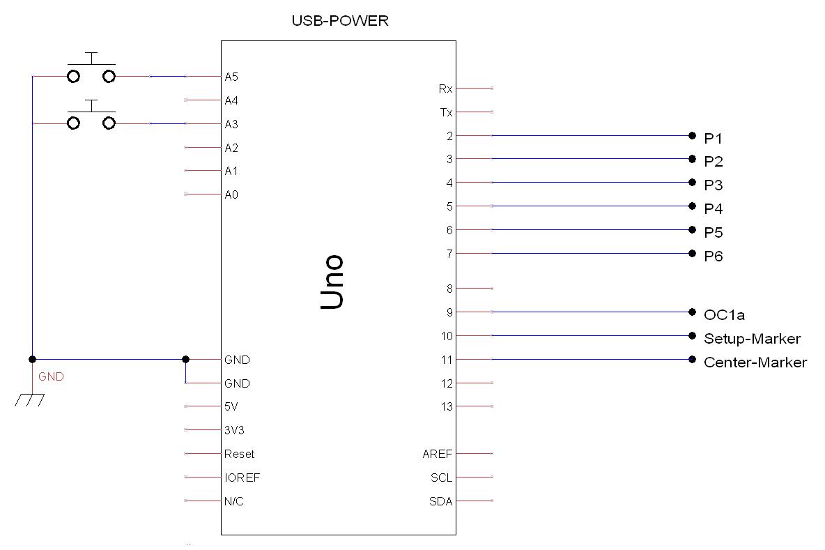
// OCR1A gets updated in COMPA-ISR !!!!!!!
}Uno Phase Shift PWM Wiring diagram
In Summary
Uno's 16-bit Timer is combined with pulse-generating code to create a 2-thru-6 channel Phase Shift PWM project. Mega, Nano, a 328 PDIP and other MCU's can support this type PSPWM. More recent 32 bit Arduino processors supporting 16-bit Timer Output Compare Interrupts should work with recalculation and appropriate code changes.
One important consideration is having Byte-Wide Port-writes line up with available Pins! Be sure to check that if you use a different MCU.
If another Interrupt service routine is executing when Timer1 hits a COMPa threshold, your Phase Shift PWM pulse gets delayed (starting or finishing) until that ISR is done! This can cause swallowed, shortened or lengthened pulses! It happens because Arduino Interrupts are usually disabled while an ISR is running. Your ISR -could- enable interrupts (while running) but its rarely done. For existing Arduino code (like that used for Timer0) you may have fun figuring out how to modify things. If you do pre-empt a running ISR, there could be consequences you didn't count on.
So, if you need this type PSPWM to 100% behave, consider using a stand-alone 328 PDIP (or Nano) and mask out Timer0 interrupts.
Have fun running Phase Shift PWM with Uno's single 16-bit Timer,
Lee