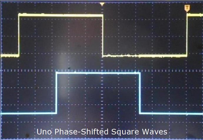
Runtime adjustable Phase-Shifted Square-Waves can be generated using Arduino Uno, Nano and Mega2560. This article shows how with Code and Schematic below.
Demo Video on YouTube.
The range of phase-shift adjustment spans Zero to 180 degrees. Timing is based on a resonator (or crystal) Clock -- making output quite stable. And being digital, you get excellent repeatability!
Early versions of RTM_TimerCalc allowed Users to adjust outputs (via GUI) across this phase range. The result from setup code was static, non-changing.
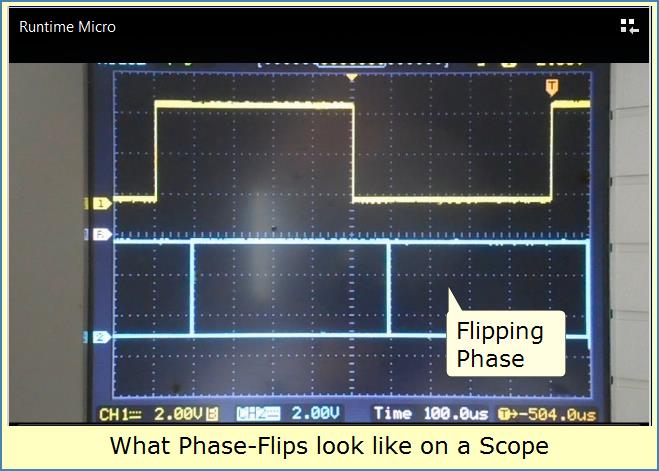
However, I failed to check what happens if someone updates phase changes during run-time. Asynchronously changing a running Timer's OCR value will eventually cause outputs to flip or invert phase -- a nasty result. This happened with RTM_TimerCalc code prior to version 1.40.
After investigation, I removed Phase-Shifted Square-Waves from RTM_TimerCalc version 1.31. I saw no way to fix the problem. But, one day, a reddit User asked a question that got me thinking.
Why Runtime Phase-Flips Happen
What could cause a Timer square-wave to suddenly invert (flip polarity) from its assigned phase-angle? The answer is loss of synchronization when changing the angle. Its caused by the waveform-generator output staying HIGH after the OCR register gets changed. Because the output isn't cleared, the next compare event flips it 180 degrees from the desired angle.
It was apparent wavegen outputs must be set LOW when changing phase angle. So how does one clear a stuck HIGH wavegen output? You can't write logic-zero to its mux-connected port-pin. It turns out Atmel included a clever way to get the job done.
Forced Output Compare Fix
The mysterious Forced Output Compare (FOC) bits in register-C can control wavegen outputs. You first set Compare register-bits for a needed match action and then force the match (Timer stopped).
Writing Logic-1 to any FOC bit causes a strobe-like event inside an associated waveform-generator. The strobe forces the target channel to immediately execute its compare-match rule. This produces a LOW -or- HIGH state at the wavegen output. Its as if a running Timer reached a compare-match.
To set wavegen outputs LOW when performing a phase change, we must do as follows;
- Stop the Timer
- Change its OCR value as needed.
- Set TCNT to zero.
- Set each channel's 2-bit Output-Compare field to the rule which causes outputs to go LOW (on a compare match).
- Force each channel's compare-match to Execute by strobing (writing 1 to) the associated FOC bits.
- Restore the 2-bit Output-Compare fields for Square Wave generation!
- Enable Timer
Now Timer phased-shifted square-waves stay predictable and behaved. There's no surprise or inverted result. You get exactly what you see on the display of RTM_TimerCalc. You'll see the same thing on PWM port-pins with an O-Scope.
By using these FOC register steps, you can dynamically adjust wavegen phase at run-time -- almost trouble-free. I say almost because the stop-start action imposed on the Timer can give your O-scope sync-jitters.
Phase-Shifted Square-Waves Project Build
So now Mode-12-CTC is back in RTM_TimerCalc V1.4. It calculates needed FOC code to keep phase-shifting stable.
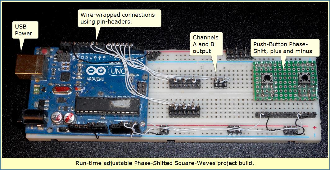
Before version release, I built a simple project on a single breadboard. It had a sticky-taped Uno, some push-buttons and header-pins to connect my Scope. Most connections used Permanent-Solderless style wire-wrap -- see next image.
Phase-Shifted Square-Waves Project Performance
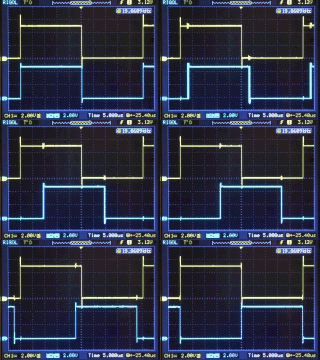
Initially I used 1000 Hz to develop this example project. But a few Readers contacted me with concerns running at higher frequencies. I updated the Code to allow easy changes for higher ranges of operation. As frequency increases, so does phase-shift step size. It becomes necessary to slow the rate and size of phase increments. Otherwise it may seem you can only achieve min and max shift positions. The updated Code allows you to select a -range- and thus have a smoother experience.
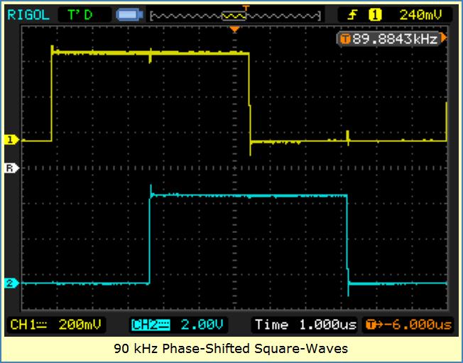
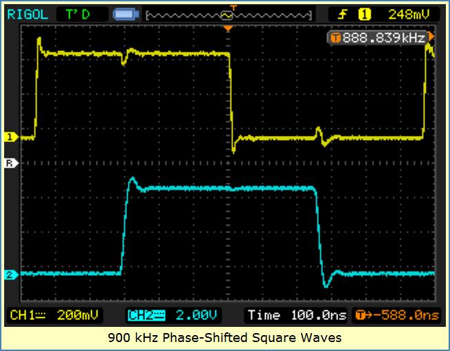
The following images reveal what waveforms look like at Ask wanted-frequency parameter entered into RTM_TimerCalc calculator Frequencies of; 1000 Hz, 90 kHz and 900 kHz. My Rigol scope was allowed to auto-pick channel settings. Note the frequency readout. Compare to RTM_TimerCalc's Actual output frequency VS the Ask parameter in TimerCalc's Report area.
Phase-Shifted Square-Waves Code
The Sketch uses TimerCalc generated code in a subroutine. A passed parameter supplies a phase-argument to increase or decrease the OCR register. Then the Timer is stopped, OCR updated and FOC gymnastics performed. Finally the Timer is allowed to run with its new OCR value.
This code runs fine on a Nano, Uno and 2560. Currently the sketch targets Nano / Uno.
Here's the Arduino Sketch to duplicate my results.
// Example Nano/Uno Code from RuntimeMicro.com
// runtime adjustable Phase-Shifted Square-Waves (1000 Hz)
// NO PHASE FLIPS
// Updated -- May 6, 2023

//============ Frequency Change Constants ==================
// Un-Comment only One line for the Phase-Chg size
const unsigned int Phase_Chg_Const = 20;   // use for 100 Hz to 50 kHz range
// const unsigned int Phase_Chg_Const = 2; // use for 50 kHz to 90 kHz range
// const unsigned int Phase_Chg_Const = 1; // use for 90 kHz to 900 kHz range

// Un-Comment only One line for the Loop-Delay-Constant
const unsigned int Delay_Const = 20;    // use for 100 Hz to 50 kHz range
//const unsigned int Delay_Const = 50;  // use for 50 kHz to 90 kHz range
// const unsigned int Delay_Const = 75; // use for 90 kHz to 900 kHz range
//================================================

int button_Pin1 = A5; // Using ADC pins for buttons on my build
int button_Pin2 = A3;

int OCR_Result; // a calculation variable

void Adjust_Phase(int Up_Down)
{
  // NOTE: This Subroutine causes Scope-Jitter when called (!!!)
  // Use Normal Sync, not Auto -- may be tricky to adjust
  // This routine is modified RTM_TimerCalc mode-12 CTC Code

  TCCR1B = 0x18; // DISABLE Timer Clock
  OCR_Result = OCR1B; // Copy current OCR value

  // change Phase
  OCR_Result += Up_Down; // add passed parameter

  // Constrain
  if (OCR_Result < 1) OCR_Result = 1; // never less than 1
  if (OCR_Result > ICR1-1) OCR_Result = ICR1-1; // never >= ICR
  OCR1B = OCR_Result; // Pass back changed Phase value

  TCNT1=0; // reset Counter
  TCCR1A = 0xA0; // Set Compare-Match bit-fields for Clear-on-Match
  TCCR1C = 0xC0; // Force Output Compares -- Clears Channel-AB Waveform Outputs!
  TCCR1A = 0x50; // Set Compare Match bit-fields for Toggle-on-Match

  TCCR1B |= 1; // Prescale=1, ENABLE Timer1 Clock
}

void setup()
{
  // PUSH BUTTON PINS -- Pins need Pulled-Up Inputs
  pinMode(A5, INPUT_PULLUP); // Push-button_Pin1 ADC pin
  pinMode(A3, INPUT_PULLUP); // Push-button_Pin2 ADC pin

  // Timer-1 16-bit, Mode-12 CTC, Top=ICR
  // 1,000 Hz Frequency, Clock is 16 MHz

  TCCR1B = 0x18; // 0001 1000, Disable Timer
  TCCR1A = 0x50; // 0101 0000

  ICR1 = 8000-1; // Frequency Control, use TimerCalc to determine! <<******

  OCR1A = 1; // never less than 1, never more than ICR1
  OCR1B = 1; // both channels in phase, OCR's not using TimerCalc values
  TCNT1=0x0;

  TCCR1A = 0xA0; // FOC setup to clear Wavegen output flops
  TCCR1C = 0xC0; // FOC strobe
  TCCR1A = 0x50; // 0101 0000

  // UNO-NANO Timer-1 Pins
   pinMode(9, OUTPUT);  // OC1a
   pinMode(10, OUTPUT); // OC1b

  // 2560 Timer-1 Pins
  // pinMode(11, OUTPUT); // OC1a
  // pinMode(12, OUTPUT); // OC1b

  TCCR1B |= 1; // Prescale=1, Enable Timer
}

void loop()
{
  int buttonState_1;
  int buttonState_2;

  // read state of pushbutton(s):
  buttonState_1 = digitalRead(button_Pin1);
  buttonState_2 = digitalRead(button_Pin2);

  delay(Delay_Const); // PACE loop speed

  // check if pushbutton pressed.
  if (buttonState_1 == LOW) Adjust_Phase(-Phase_Chg_Const); // Decrease Phase Angle

  // check if pushbutton pressed.
  if (buttonState_2 == LOW)  Adjust_Phase(+Phase_Chg_Const); // Increase Phase Angle
}
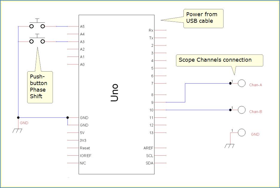
Phase-Shifted Square-Waves Diagram
This wiring matches up with the previous code listing -- next image.
Image Path: /sites/default/files/Page-Images/Phase-Shifter%20Schematic.jpg
Alt Text: Image shows Phase-Shifted Square-Waves project schematic.
Phase-Shift Math for Arduino Nano, Uno and Mega2560
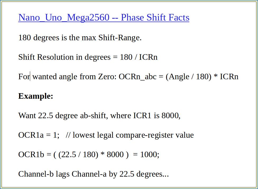
You might wonder how to calculate a specific phase-shift between output Channels. Its fairly easy once you realize shifts are relative to the Timer start count. In mode-12, the Timer starts at zero. But zero causes problems in output-compare registers! So a tradeoff is use 1 for the lowest possible shift from the Timer start.
There are more considerations like phase-shift range, shift resolution and calculating a specific shift angle. I've summarized what I think are proper formulas for making these calculations. Please see the following Image.
In Summary
Runtime adjustable Phase-Shifted Square-Waves can be generated using Arduino Nano, Uno and Mega2560. The 16-bit Timers give decent performance, range, repeatability and resolution. Once adjusted, Square-Wave output is as stable as the clock system itself.
Earlier versions of RTM_TimerCalc lacked the FOC code which prevents the phase-flip flaw. Version 1.4 and later generate needed FOC code to ensure run-time phase-shift projects operate properly.
Here's a YouTube Video showing many abilities and features of RTM_TimerCalc V1.4.
Lee
