This 90-degree Phase Shift PWM (PSPWM) experimenter's project has controls for Start, Stop, Direction and Duty-adjust. It can be configured to run from 50 Hz up to 80 kHz. Use it to generate 2, 3, or 4 PSPWM channels with full duty-cycle range. There's plenty to cover, so, let's dive in...
Accurate 90-degree Phase Shift PWM
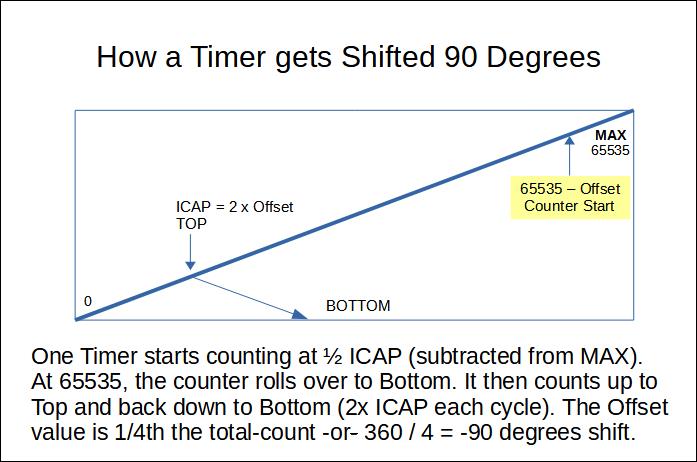
Previous (Mega based) Runtime Micro projects achieved Phase Shift using a delayed-start mechanism. But shift accuracy suffered at tens-of-kilohertz frequencies. Luckily there's another phase-shift method using a numerically offset TCNT Timer register.
To maintain accurate 90-degree shift, we choose frequencies whose ICAP ( Input Capture ) register -- values are exactly divisible by 2. The TCNT register is initially offset to a value of (65535 - (ICAP / 2)). Since mode-10 PWM counts ICAP twice per cycle, this 'offset' corresponds to 1/4th the full count period. If the period of (2 x ICAP) equals 360 degrees, it follows (ICAP / 2) equates to 90 degrees. Both Timers start in the same instant -- but the offset Timer must first count to 65535 before cycling normally. The result is a precise 90-degree phase shift. See next image...
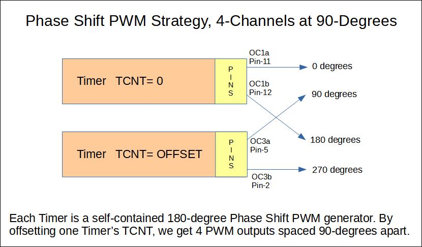
90-Degree Phase Shift PWM Strategy
Using two 16-bit Timers, we get full duty-range PSPWM. It may surprise you to learn each Timer generates its own 180 degree PSPWM signal-pair. If we phase shift one Timer 90-degrees, the combined output delivers 4 channels spaced 90-degrees apart. The next image depicts this relationship...
Control and Configuration
This project adds Interface elements in the form of;
- Start and Stop push-buttons.
- Duty increase and decrease push-buttons.
- Forward or Reverse slide-switch.
For some experimenting situations, it may be helpful to have Reverse-direction capability. A quick way to Start-or-Stop might be important too. Low-value duty-cycle could be necessary before acting on Start-or-Stop commands. Plus, there might be a need to limit duty-cycle to some maximum value.
To address these possibilities, project Code has the following Configuration selections;
- Duty-Ramp-down action before Stop.
- Duty-Limit: 25% (or just below using dead-time).
- Start-up duty of (2, 10 or 25 percent)
- Fixed or Switched direction-control.
- 14 possible PSPWM Frequencies (from 50 Hz to 80 kHz)
- A DEBUG #define for Serial reports of configuration-status and start-stop actions
All these configuration changes require re-compile and upload.
90-degree Phase Shift PWM Performance
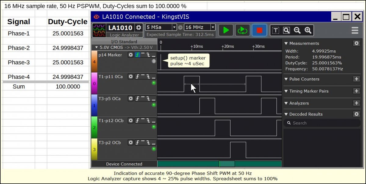
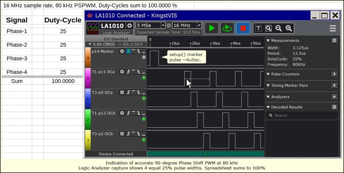
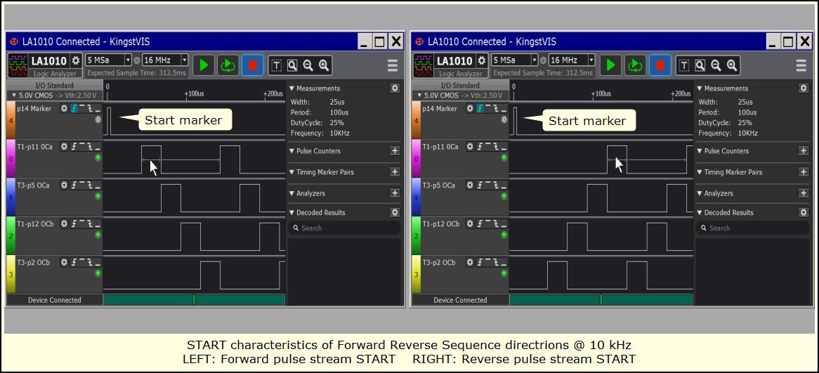
Proof of performance is presented as snapshots from a Logic Analyzer. The approach to confirm 90-degree shift-accuracy (aside from the math for offset) was check if 25% duty delivered 4 equal-width pulses per period.
Logic Analyzer duty-cycle values were entered into a spreadsheet and summed to evaluate results. At 50 Hz, the variances (from 25%) were very tiny but when added together came out to exactly 100.0000%. At 80 kHz, the duty values were exact (no fractional variances), and still added to 100.0000%. IMO, this is a reasonable indication of good 90-degree accuracy. The math and the measurements seem to agree.
Here are the performance snapshots.
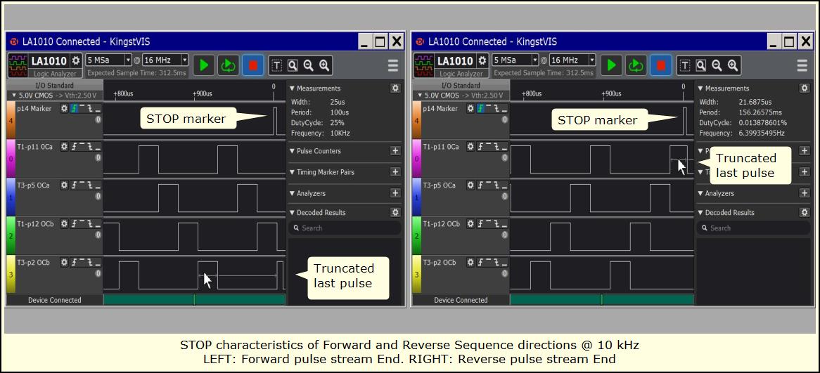
When starting this PSPWM build, you can expect the first-channel to lead the second-channel and so on. There are no garbage start-up pulses. Output begins at the respective first channel pin (direction dependent). On Stop, the pulse stream ends asynchronously. Pulse widths should remain at correct Duty-width except possibly the very last pulse. It will be the correct size or smaller -- never larger!
NOTE: though the truncated pulses shown above may seem to routinely happen at the end of a 4-phase sequence, this is not the case. The last pulse can occur anywhere in the sequence.
90-degree Phase Shift PWM Build
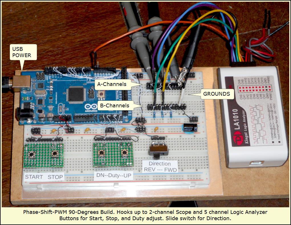
The project was assembled using a sheet metal ground-plane cemented to a 5 x 10 inch piece of medium-density-fiberboard (MDF). A pair of BB-830 breadboards were fitted with their included back-plates and cemented atop the ground-plane. A strip of aluminum foil beneath breadboard back-plate joins ensured they were well connected (to each other) and making good contact with ground-plane. From there, I sticky-taped the Mega 2560 to one end of a breadboard. Next I populated the surrounding area with needed headers, components, switches, etc.
Permanent-Solderless wire-wrap made 99% of connections. There was extra MDF space to fit the Logic-Analyzer pod, so I sticky taped it. A construction trick combining 2-row single-side headers with spaced-apart double-side pins realized rugged breadboard output test-points. The result is quite robust. Here's the image...
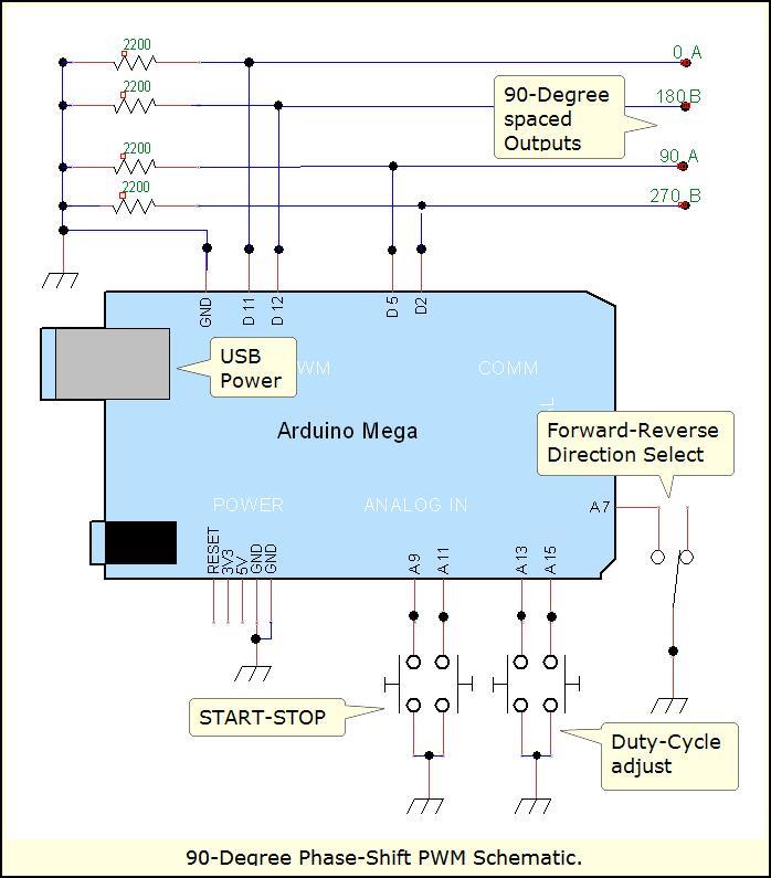
90-degree Phase Shift PWM Schematic
The schematic shows pull-down resistors. They are important for clean Start and Stop operation. What isn't shown is the marker-pulse pin (D-14) used to trigger Logic-Analyzer capture. Its there if you need it.
90-degree Phase Shift PWM Code
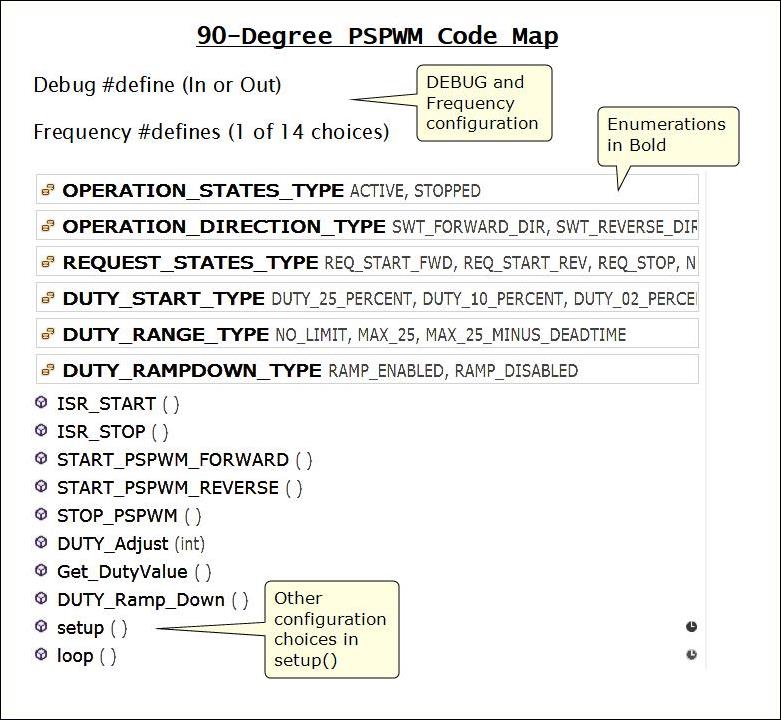
This project's code is more involved than previous PSPWM projects. Its a bit long to list here. You can download it as a Zip-file at the bottom of this page. In that file you'll find a Code-Map (shown next).
The map calls out Configuration areas and shows general code structure. It should help with finding a specific section or subroutine. Map items are listed as they occur in code.
Please Note: the Code uses GreyGnome's EnableInterrupt library to sense push-button events. If you get a "missing EnableInterrupt.h" Error, Download the library and use your Arduino IDE to install it. After that, a recompile of the project code should work fine.
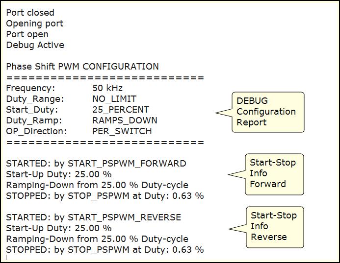
Please know if DEBUG is #defined, extra code delivers reports of current-configuration over Serial. It also outputs information when you Start or Stop the system. See the next image for a sample of DEBUG output on my Visual-Studio IDE...
The compiler reports this sketch (including DEBUG) uses 9806 bytes of Flash (4%) and a minimum of 340 bytes SRAM (4%).
One more thing regarding this code...
No 60 Hz Frequency
You may wonder what happened to the usual inclusion of 60 Hz. Well, it's ICAP (aka ICRn) won't divide exactly by 2. To get an accurate 90-degree PSPWM at 60 Hz, it appears one must change the Mega clock to 12 MHz. RTM_TimerCalc lets you confirm this calculation using its Custom Clock selection (set to 12E6 or 12000000). Then you'd input your ASKt parameter for for 60 Hz Mode-10 on a 16-bit Timer. An ICAP value of 12500 gets calculated which divides nicely by 2 resulting in a value of 6250.
If you're -really- brave and want to chop-out your Mega's 16-MHz resonator (a tiny component) and hook up an external 12 MHz clock (-gulp-), then it appears you can get accurate 60 Hz operation. But this is an extreme undertaking to perform on a working Mega. IDK-for-sure if its a workable idea, I have not tried it here. FWIW.
In Summary
We've seen how two 16-bit Timers from a Mega 2560 deliver decent accuracy 90-degree Phase Shift PWM signals. The tactic of ICAP (ICRn) divisible by 2 ensures a more precise Phase-Offset and well behaved pulse characteristics. Shift-accuracy holds all the way to 80 kHz! Performance snapshots document these results.
RTM_TimerCalc provided portions of Timer setup code (as well as ICAP calculations). Pull-down resistors (2200 Ohm) override port-pin float tendencies. Don't forget them if you apply this project to real-world control! Using the example Schematic and Sketch, it should be straight-forward to duplicate this project.
Project code was developed in Windows-7 using Visual-Studio Community Edition v2015 along with Visual-Micro's (Arduino-for-Visual-Studio) add-in. When I can get a video of this project up, you'll see this IDE in action.
PLEASE NOTE: Like other PSPWM Phase Shift PWM Projects found here at Runtime Micro, this project delivers Fixed-Frequency, Fixed-Phase-Shift characteristics. The only run-time variable is duty-cycle.
Have fun experimenting with 90-degree Phase Shift PWM.
Lee

