
Here's a 6-channel 60-degree Phase Shift PWM (PSPWM) project. It takes 4 Timers at start-up but only needs 3 once running. Three of four Timers use Mode-10-Phase PWM to develop PSPWM output. Each supplies 2-Channels 180 degrees apart. Timer5 delay-starts Timer3 and Timer4 to achieve the 60 degree phase delta. This is explained in more detail below.
Tactics for a 6-Channel Phase Shift PWM Project
When we speak of Phase shift, we're describing a time-difference for signals of known frequency. For example, 1000 Hz has a period of 1000 uSec. If we delay a second 1000 Hz signal (relative to the first) for 166.6 uSec, we shift its phase 166.6/1000 giving us 360/6 = 60 degrees. This means we can Phase Shift PWM using Timers with delayed start times.
This project uses four 16-bit Timers from a Mega 2560. They're set to the same frequency but start at different times to get desired phase-shifts. This approach works since the 2560 architecture uses a common clock and synchronous counters.
Timer waveform generators are set for Mode-10 (Phase PWM). This mode is sometimes called center-symmetric. The counter changes direction in the center of a generated pulse (which can be used to trigger an Interrupt). This means ISR routines could sample Voltage or Current at PWM pulse center points.
Code Strategy to Phase Shift PWM
Using four 16-bit Timers, we start Timer-5 and Timer-1 at the same instant. Timer-5 delay-starts Timer-3 and Timer-4 in 60 degree steps via its COMPA and COMPB Interrupts. Know that Timer-5 uses Fast-PWM single-slope counting for this task. The Fast-PWM mode has more resolution compared to Phase-PWM. That could be handy if we needed to tweak start-delays.

This scheme works but there's a snag -- unwanted startup pulses. The Timers don't seem well behaved until they make it through one full cycle. After that, things look OK.
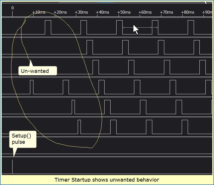
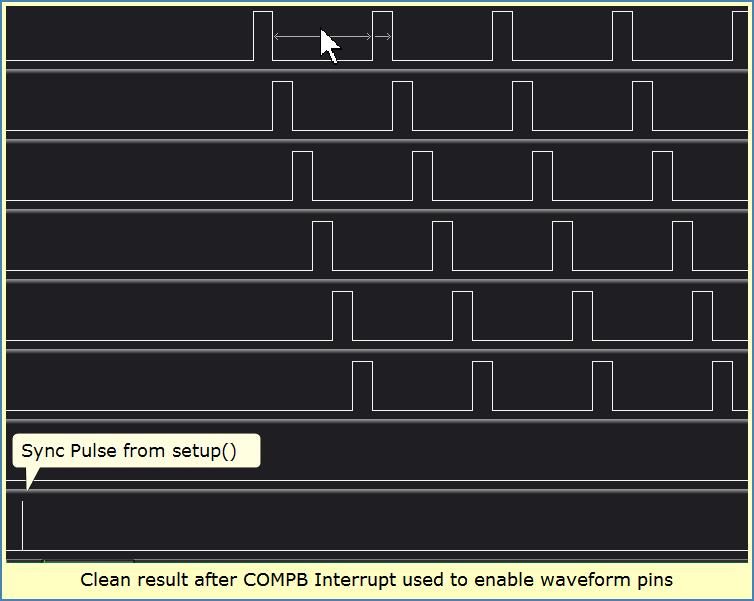
To get around start-up problems, I used the COMPB interrupt of Timer-4 to delay-enable Timer waveform output pins. This means the unwanted outputs were still happening but not appearing on the output pins. This tactic provides a clean startup. For a predictable shut-down, you could use the same Interrupt to disable waveform pins.
Please Note: You may need low duty cycle PWM (no waveform overlap) for start-up and shut-down to be predicable.
Phase Shift PWM Project Build
I sticky-taped a Mega2560 to an 830 type breadboard. Permanent-Solderless style wire-wrap made needed connections. Power was supplied via USB cable. Modified double-sided header pins were used for logic-analyzer test-points. I borrowed a push-button assembly from a previous project. It plugged into the breadboard. The result is quite solid.

Mirrored Duty-Cycle Adjust
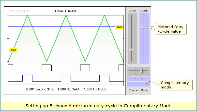
All 6 channels need to have the same pulse width. When you inspect this project's Code, you'll find odd duty-cycle math on B-channels. The A-channels use a straight-forward duty calculation. But Timer B-channels are programmed to operate in a complimentary (180 degree opposite) fashion. This puts PWM pulses in the correct relative position. But to get correct B-channel pulse-width, we must specify a mirrored duty-value.
For example, an A-channel duty of 30% requires the B-channel use 70%. An A-channel duty of 20% requires B-channel use 80%. Notice how the A and B duty values always add to 100%. In this fashion, Timer pulses hold the same width while being positioned as needed.
As in the previous 3-phase project, I used RTM_TimerCalc to generate much of the setup code for Timers 1, 3, 4 and 5. TimerCalc's chart helped me visualize mirrored duty-cycle too (see image at end of this page for an example).
Phase Shift PWM Code
This project's Code is set to use 1 of 4 different frequencies; 50, 60, 300 and 500 Hz. The first three may relate to motor control projects. If you un-comment a frequency #define statement, the compiler will set your Frequency accordingly. You could add other frequencies if you like writing pre-processor code. Just be aware going really high in frequency could cause problems. I recommend using TimerCalc to keep your numbers straight...
Here's the project Code;
// 6-Channel Phase Shift PWM Code from Runtime Micro
// Uses Mega2560 16 bit Timers 1, 3, 4 and 5. 60 degree shifts
// Timer setup code generated by RTM_TimerCalc v1.4
/////////////////////////////////////////////////////////////////////////////
// UN-COMMENT FREQUENCY DESIRED
//#define TIMER_FREQ_50HZ
//#define TIMER_FREQ_60HZ
#define TIMER_FREQ_300HZ
//#define TIMER_FREQ_500HZ
////////////////////////////////////////////////////////////////////////////
#if defined TIMER_FREQ_50HZ
int const ICAP_NDiv=20000;
int const T5_ICAP=40000-1;
int PRESCALE = 2;
int ADJ_CONST = 10;
int WAIT_CONST = 70;
#elif defined TIMER_FREQ_60HZ
int const ICAP_NDiv=16667;
int const T5_ICAP=33333-1;
int PRESCALE = 2;
int ADJ_CONST = 10;
int WAIT_CONST = 70;
#elif defined TIMER_FREQ_300HZ
int const ICAP_NDiv=26667;
int const T5_ICAP=53333-1;
int PRESCALE = 1;
int ADJ_CONST = 50;
int WAIT_CONST = 20;
#elif defined TIMER_FREQ_500HZ
int const ICAP_NDiv=16000;
int const T5_ICAP=32000-1;
int PRESCALE = 1;
int ADJ_CONST = 25;
int WAIT_CONST = 20;
#endif
/////////////////////////////////////////////////////////////////////////////
// Handy Variables
int btn_DutyIncrease_Pin = A13; // Using ADC pins for push-buttons
int btn_DutyDecrease_Pin = A15;
int OCR_Result; // a calculation variable
int const Duty_Numeric_Boundary = 20; // Numeric LIMIT for adjustable duty range
/////////////////////////////////////////////////////////////////////////////
ISR(TIMER5_COMPA_vect)
{
TCCR3B |= PRESCALE; // DELAYED START Timer 3, 60 degrees
}
ISR(TIMER5_COMPB_vect)
{
TCCR4B |= PRESCALE; // DELAYED START Timer 4, 120 degrees
TIMSK5=0x0; // STOP Interrupts from Timer5
}
ISR(TIMER4_COMPB_vect)
// ENABLE WAVEFORM PINS ONCE TIMERS STABILIZE
{
pinMode(11, OUTPUT); // OC1a, 0 degrees phase shift
pinMode(12, OUTPUT); // OC1b, 180
pinMode(5, OUTPUT); // OC3a, 60 degrees from Timer-3
pinMode(2, OUTPUT); // OC3b, 240 degrees from Timer-3
pinMode(6, OUTPUT); // OC4a, 120 degrees from Timer-4
pinMode(7, OUTPUT); // OC4b, 300 degrees from Timer-4
TIMSK4=0x0; // STOP Interrupts from Timer4
}
void setup() // ********
{
// PUSH BUTTON PINS need Pulled-Up Inputs
pinMode(btn_DutyIncrease_Pin, INPUT_PULLUP); // Push-button on ADC pin
pinMode(btn_DutyDecrease_Pin, INPUT_PULLUP); // Push-button on ADC pin
pinMode(14, OUTPUT); // Marker Pulse pin
// Set Timer-5 freq SAME as other Timers!
// Using mode-14 FAST-PWM, single slope, up counter
TCCR5B = 0x18; // 0001 1000, Disable Timer
TCCR5A = 0x02; // 0101 0000
ICR5 = T5_ICAP;
TCNT5=0x0;
OCR5A = (int) (ICR5 * 0.166666); // 60 degrees at Freq
OCR5B = (int) (ICR5 * 0.333333); // 120 degrees at Freq
TCNT5=0x0;
TIMSK5 = 0x06; // Enable CompA and CompB Interrupts <<**********************
/////////////////////////////////////////////////////////////////////////////
// Timer-1 16-bit, Mode-10 Phase, Top=ICR
// Clock is 16 MHz
TCCR1B = 0x10; // 0001 1000, Disable Timer
TCCR1A = 0xB2; // 1000 0010
ICR1 = ICAP_NDiv;
OCR1A = (int) (ICR1 * 0.166666);
OCR1B = (int) (ICR1 * 0.833333);
TCNT1=0x0;
/////////////////////////////////////////////////////////////////////////////
// Timer-3 16-bit, Mode-10 Phase, Top=ICR
// Clock is 16 MHz
TCCR3B = 0x10; // 0001 1000, Disable Timer
TCCR3A = 0xB2; // 1010 0010
ICR3 = ICAP_NDiv;
OCR3A = (int) (ICR3 * 0.166666);
OCR3B = (int) (ICR3 * 0.833333);
TCNT3=0x0;
/////////////////////////////////////////////////////////////////////////////
// Timer-4 16-bit, Mode-10 Phase, Top=ICR
// Clock is 16 MHz
TCCR4B = 0x10; // 0001 1000, Disable Timer
TCCR4A = 0xB2; // 1010 0010
ICR4 = ICAP_NDiv;
OCR4A = (int) (ICR4 * 0.166666);
OCR4B = (int) (ICR4 * 0.833333);
TCNT4=0x0;
TIMSK4 = 0x04; // Interrupt to enable Output Pins
digitalWrite(14, HIGH); // MARKER PULSE <<-----------------------------
digitalWrite(14, LOW);
// UPDATE 9-21-2022 by stockvu
// Synchronize Start of Timers 1 and 5
GTCCR=0x81; // Timer Sync Control -- STOP ALL TIMERS, Clear preScalers
TCCR5B |= PRESCALE; // Prescale=X, ENABLE Timer 5 clock
TCCR1B |= PRESCALE; // Prescale=X, ENABLE Timer 1 clock
GTCCR=0x0; // START ALL TIMERS
} // end setup
void PWM_adjust(int up_down) // Adjust PWM-duty on Timers Together T1, T3 and T4
{
// calculate
OCR_Result = OCR1A;
OCR_Result += up_down;
// constrain (old-school style), OCRs can never be < 1 or >= ICR !
if (OCR_Result < Duty_Numeric_Boundary) OCR_Result = Duty_Numeric_Boundary;
if (OCR_Result > ICR1-Duty_Numeric_Boundary) OCR_Result = ICR1-Duty_Numeric_Boundary;
// Assert regular Duty Cycle to A-channels
OCR1A = (int) OCR_Result;
OCR3A = (int) OCR_Result;
OCR4A = (int) OCR_Result;
// Assert mirrored Duty Cycle to B-channels
OCR1B = (int) ICR1-OCR_Result;
OCR3B = (int) ICR1-OCR_Result;
OCR4B = (int) ICR1-OCR_Result;
}
void loop() // ********
{
int state_DutyIncrease;
int state_DutyDecrease;
// read state of pushbutton(s):
state_DutyIncrease = digitalRead(btn_DutyIncrease_Pin);
state_DutyDecrease = digitalRead(btn_DutyDecrease_Pin);
// check if pushbutton pressed.
if (state_DutyIncrease == LOW)
{
PWM_adjust(+ADJ_CONST);
delay(WAIT_CONST); // PACE loop speed a bit
}
// check if pushbutton pressed.
if (state_DutyDecrease == LOW)
{
PWM_adjust(-ADJ_CONST);
delay(WAIT_CONST); // PACE loop speed a bit
}
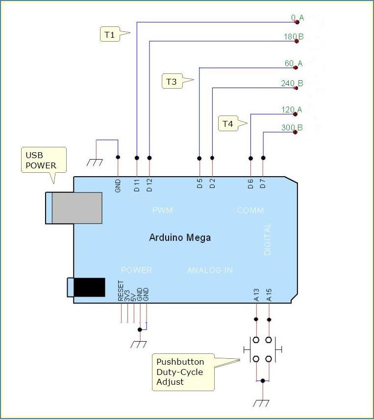
}// end loop()Phase Shift PWM Project Diagram
The diagram doesn't show the pin used for a marker pulse generated in setup(). That pin is D14. Code already pinMode's it and generates the marker pulse.
RTM_TimerCalc Visual Display
I never would have realized this type of project was possible were it not for RTM_TimerCalc's chart. Seeing pulses mirrored in duty-cycle always fascinated me. I wondered why Atmel designed Timers this way. Now things are a bit clearer...
Here's a YouTube video showing many abilities and features of RTM_TimerCalc V1.4.
Lee