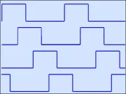
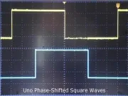
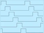
I was looking for ways to demonstrate RTM_TimerCalc and came across the idea to phase shift PWM. At first, I was surprised by the concept. But apparently phase-shifted PWM has useful applications.
I read about a Phase Shift PWM approach using 3 signals set 120 degrees apart. I decided to try making a 3 x 120 degree Project using an Arduino Mega2560.
The following animation shows 2 (of the 3) varying PWM project signals spread 120 degrees apart at 1000 Hz. Its possible we don't need to vary Duty-cycle but it helps to see the PWM is phase shifted.
Phase Shift PWM Project Design
The only way I saw to get 120 degree Phase Shift PWM was use 4 separate Timers. One Timer would delay start several others. All 4 Timers would use a cycle frequency of 1000 Hz. I discovered using Fast-PWM for the delay-start Timer was better overall. The 3 waveform Timers use Phase-PWM mode.
Since this was a 3-channel project, each phase-shifted Timer delivered output from its channel-A. Channels B and C are available for Interrupt or general PWM use.
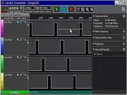
The next image shows resulting phase shift PWM captured on a logic analyzer.
Phase Shift PWM Project Build
I sticky taped a Mega2560 to an 830 type breadboard. Permanent-Solderless style wire wrap made needed connections. Power was supplied via USB. And some modified double-sided header pins made several test-points. (See next Image)
I borrowed a push-button assembly from my previous Phase Shifted Square Waves project. It plugged into the breadboard and wiring was straight forward.
Phase Shift PWM Code Strategy
Timer-5 synchronizes two of three Timers in 120 degree steps. This requires starting Timer-5 and Timer-1 at nearly the same moment. EDIT: Now have synchronized-start using General Timer Register.
Then Timer-5 Interrupt ISR's enable Timer-3 and Timer-4 at 120 degree Intervals. I hooked up the O-Scope to the test-point pins and saw waveforms separated by 120 degrees. They were rock solid!
Next I added code for push-buttons to vary the 3 channels of PWM duty cycle. I could change duty-cycle for any one channel or all three together. I left the code to change all three.
But there were concerns. At 100% and 0% duty, the scope traces were twitchy. I added OCR limits to avoid getting to zero or the ICR value. Then I could see tiny pulses at either duty-cycle extreme.
120 degree Phase-Shift Code (Updated)
RTM_TimerCalc generated most of the code for Timers 1, 3, 4 and 5. I pasted it into needed setup() blocks. I did remove some Timer enable statements. But now there are some revisions to discuss -- see next.
Pulse Center Markers
In my first Code version, all Timers used Fast-PWM mode. But after making a 6-phase project, I learned mode-10 is better to Phase Shift PWM Timers. The delay Timer still remains in Fast-PWM mode -- as it has twice the resolution of Phase-mode.
One reason to use Phase-mode PWM is its center-symmetric nature. The revised code exploits this by having waveform Timers generate Overflow Interrupts at channel-A pulse centers. You can use these Interrupts to sample signals at pulse middle points! In a motor control application, this could trigger a measurement of Voltage or Current.
The Code uses Overflow Interrupts to generate marker-pulses at Port-Pins. A logic-analyzer connected to those pins proves Interrupts occur center-pulse. This also reveals regardless of duty-cycle, channel-to-channel markers remain 120 degrees apart. Please see the next image.
Phase Shift PWM Start-up
Initially I only considered how this project looked on a scope or analyzer while running. But in the follow-up 6 Phase Project, I discovered unwanted start-up behavior just after running setup(). I could spot setup's position in time by adding a Port-Pin marker-pulse. It triggered logic-analyzer capture. The revised Code includes that pulse marker.
I was surprised to see a clean 3-phase start-up. So, I didn't add any code to delay enable of PWM pins.
But if you build this project with intent to control some sort of hardware, consider how you'll shut it down. You might arrange a COMPB interrupt on Timer-4 to signal a good time to disable Timer output pins. Just a thought...
Changing PWM duty-Cycle
Varying PWM looks easy since Atmel designed the Timers to double-buffer changes to OCR registers. This means glitch-free updates to duty-cycle from Code.
But keep in mind the time-delay nature of this project means each phase updates at 120 degree time-spacing! It'll take at least 1 full Timer period for all three channels to assume a new pulse-duty value. : /
Phase Shift PWM Example Code
Here's the (revised 9-19-2022) project Code listing;
// REVISED 3-Channel, 120 Degree Phase Shift PWM code from Runtime Micro // Uses 4 Mega2560 16-bit Timers, T5 @ mode-14-FAST, T1, T3 and T4 @ Mode-10-PHASE // Timer setup code generated by RTM_TimerCalc v1.4 int btn_DutyIncrease_Pin = A13; // Using ADC pins for push-buttons int btn_DutyDecrease_Pin = A15; int OCR_Result; // a calculation variable int const Duty_Limit = 20; // Numeric LIMIT for 0% or 100% duty //////////////////////////////////////////////////////////////////////// ISR(TIMER5_COMPA_vect) { TCCR3B |= 1; // DELAYED START Timer 3, 120 degrees } ISR(TIMER5_COMPB_vect) { TCCR4B |= 1; // DELAYED START Timer 4, 240 degrees TIMSK5 = 0x0; // STOP further Interrupts from Timer5 } //////////////////////////////////////////////////////////////////////// // Center Pulse Marker Routines for 120 degree channels // Used by Logic Analyzer, adapt for S&H measurements ISR(TIMER1_OVF_vect) { digitalWrite(14, HIGH); // Center Pulse Marker T1-A digitalWrite(14, LOW); } ISR(TIMER3_OVF_vect) { digitalWrite(15, HIGH); // Center Pulse Marker T3-A digitalWrite(15, LOW); } ISR(TIMER4_OVF_vect) { digitalWrite(16, HIGH); // Center Pulse Marker T4-A digitalWrite(16, LOW); } //////////////////////////////////////////////////////////////////////// void setup() { // PUSH BUTTON PINS need Pulled-Up Inputs pinMode(btn_DutyIncrease_Pin, INPUT_PULLUP); // Push-button on ADC pin pinMode(btn_DutyDecrease_Pin, INPUT_PULLUP); // Push-button on ADC pin // Timer-5 16-bit, Mode-14 FAST, Top=ICR // 1000 Hz Frequency, Clock is 16 MHz // Only this Timer is using Fast-PWM TCCR5B = 0x18; // 0001 1000, Disable Timer TCCR5A = 0x50; // 0101 0000 ICR5 = 16000 - 1; OCR5A = (int)(ICR5 * 0.33333); // 120 degrees at Freq OCR5B = (int)(ICR5 * 0.66666); // 240 degrees at Freq TCNT5 = 0x0; TIMSK5 = 0x06; // Enable CompA and CompB Interrupts ////////////////////////////////////////////// // Timer-1 16-bit, Mode-10 Phase-PWM, Top=ICR // 1,000 Hz Frequency, Clock is 16 MHz TCCR1B = 0x10; // 0001 1000, Disable Timer TCCR1A = 0x82; // 1000 0010 ICR1 = 8000 - 1; OCR1A = (int)(ICR1 * 0.33333); TCNT1 = 0x0; TIMSK1=0x01; // OVF Channel-A Center Pulse Interrupt pinMode(11, OUTPUT); // OC1a, 0 degrees phase shift ////////////////////////////////////////////////// // Timer-3 16-bit, Mode-10 Phase, Top=ICR // 1,000 Hz Frequency, Clock is 16 MHz TCCR3B = 0x10; // 0001 1000, Disable Timer TCCR3A = 0x82; // 1010 0010 ICR3 = 8000 - 1; OCR3A = (int)(ICR3 * 0.33333); TCNT3 = 0x0; TIMSK3=0x01; // OVF Center Pulse Interrupt pinMode(5, OUTPUT); // OC3a, 120 degrees from Timer-1 /////////////////////////////////////////////////// // Timer-4 16-bit, Mode-10 Phase, Top=ICR // 1,000 Hz Frequency, Clock is 16 MHz TCCR4B = 0x10; // 0001 1000, Disable Timer TCCR4A = 0x82; // 1010 0010 ICR4 = 8000 - 1; OCR4A = (int)(ICR4 * 0.33333); TCNT4 = 0x0; TIMSK4=0x01; // OVF Center Pulse Interrupt pinMode(6, OUTPUT); // OC4a, 240 degrees from Timer-1 // Center Pulse Marker Pins pinMode(14, OUTPUT); // Center-Pulse Marker T1-Channel-A pinMode(15, OUTPUT); // Center-Pulse Marker T3-Channel-A pinMode(16, OUTPUT); // Center-Pulse Marker T4-Channel-A pinMode(18, OUTPUT); // Setup Marker Pulse // UPDATE // Synchronize Start of Timers 1 and 5 GTCCR=0x81; // Timer Sync Control -- STOP ALL TIMERS, Clear preScalers TCCR5B |= 1; // Prescale=1, ENABLE Timer 5 TCCR1B |= 1; // Prescale=1, ENABLE Timer 1 GTCCR=0x0; // START ALL TIMERS // Place Marker Pulse to watch Timer(s) startup digitalWrite(18, HIGH); digitalWrite(18, LOW); } // end setup void PWM_adjust(int up_down) // Adjust PWM on Timers T1, T3 and T4 { // calculate OCR_Result = OCR1A; OCR_Result += up_down; // constrain old-school style if (OCR_Result < Duty_Limit) OCR_Result = Duty_Limit; // OCR cannot be less than 1 if (OCR_Result > ICR1 - Duty_Limit) OCR_Result = ICR1 - Duty_Limit; // OCR cannot be at or more than ICR // Assert new Duty Cycle to Timers double-buffered OCRs OCR1A = (int)OCR_Result; OCR3A = (int)OCR_Result; OCR4A = (int)OCR_Result; } // end PWM_adjust void loop() { int state_DutyIncrease; int state_DutyDecrease; // read state of pushbutton(s): state_DutyIncrease = digitalRead(btn_DutyIncrease_Pin); state_DutyDecrease = digitalRead(btn_DutyDecrease_Pin); delay(10); // PACE loop speed a bit // check if pushbutton pressed. if (state_DutyIncrease == LOW) { PWM_adjust(+20); } // check if pushbutton pressed. if (state_DutyDecrease == LOW) { PWM_adjust(-20); } } // end loop()
Phase Shift PWM Diagram
The diagram does not show marker pulse pins. They are D14, D15, D16 and (D18 for setup pulse). You can safely remove marker Interrupts and/or pinMode code as you see fit.
Other Phase Shift PWM Angles
Timer-5 OCR thresholds of 1/3 and 2/3 (of ICR) made possible delayed starting for 120 degree phase shifts. Changing OCR values for 1/4 can buy you 90 degree shift. Many different phase-shift arrangements are possible. These fractions are independent of Timer cycle frequency. The thing to avoid is low N-Divide values. Lower frequencies require larger N-Divides. The opposite is true as you go up in frequency.
With RTM_TimerCalc you can visualize waveforms, inspect N-Divide calculated values and create needed code. Here's a short Video covering RTM_TimerCalc v1.4 -- revealing its latest capabilities and features.
Have fun Phase-Shifting PWM
Lee
Created: Aug 29, 2022 Updated: Jan 11, 2024 |